Projection Drawing
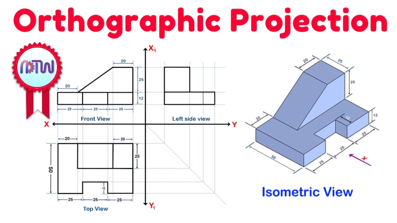
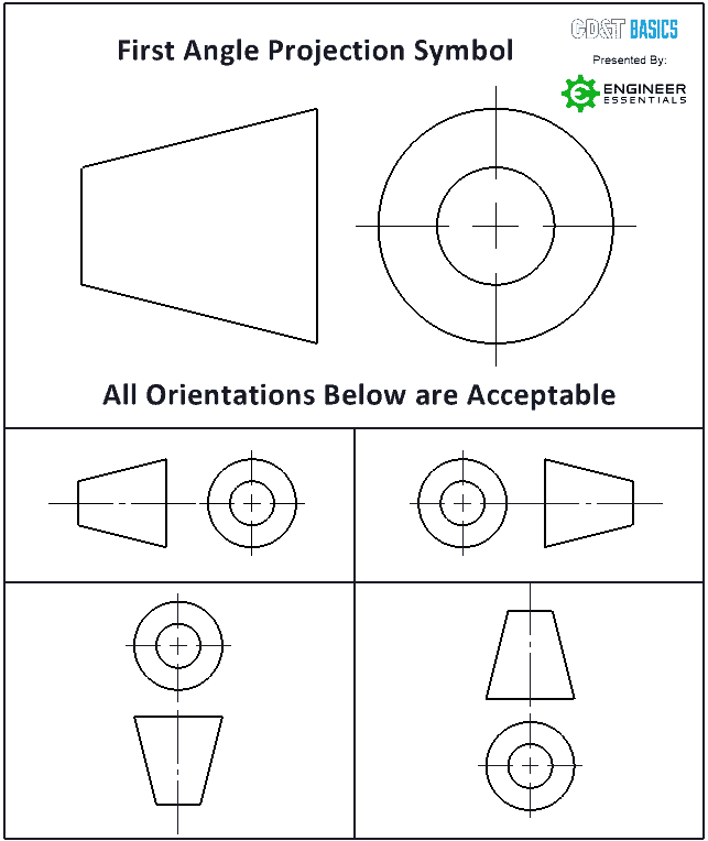
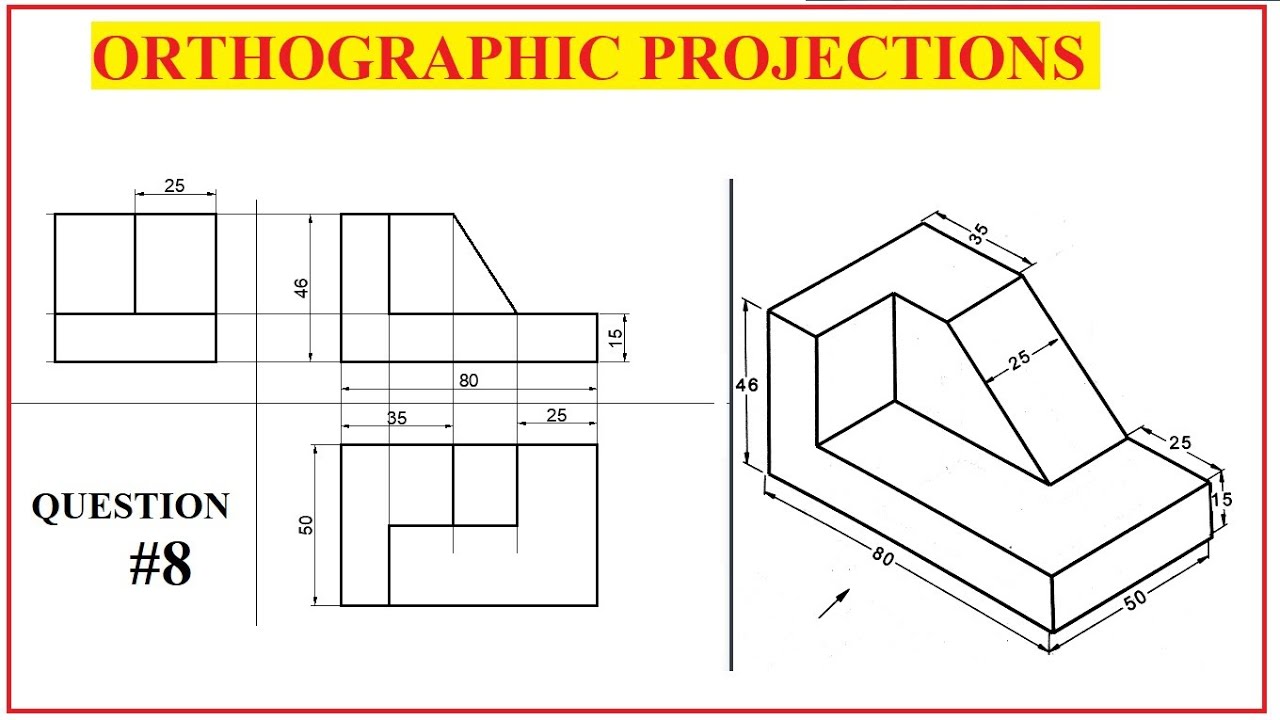
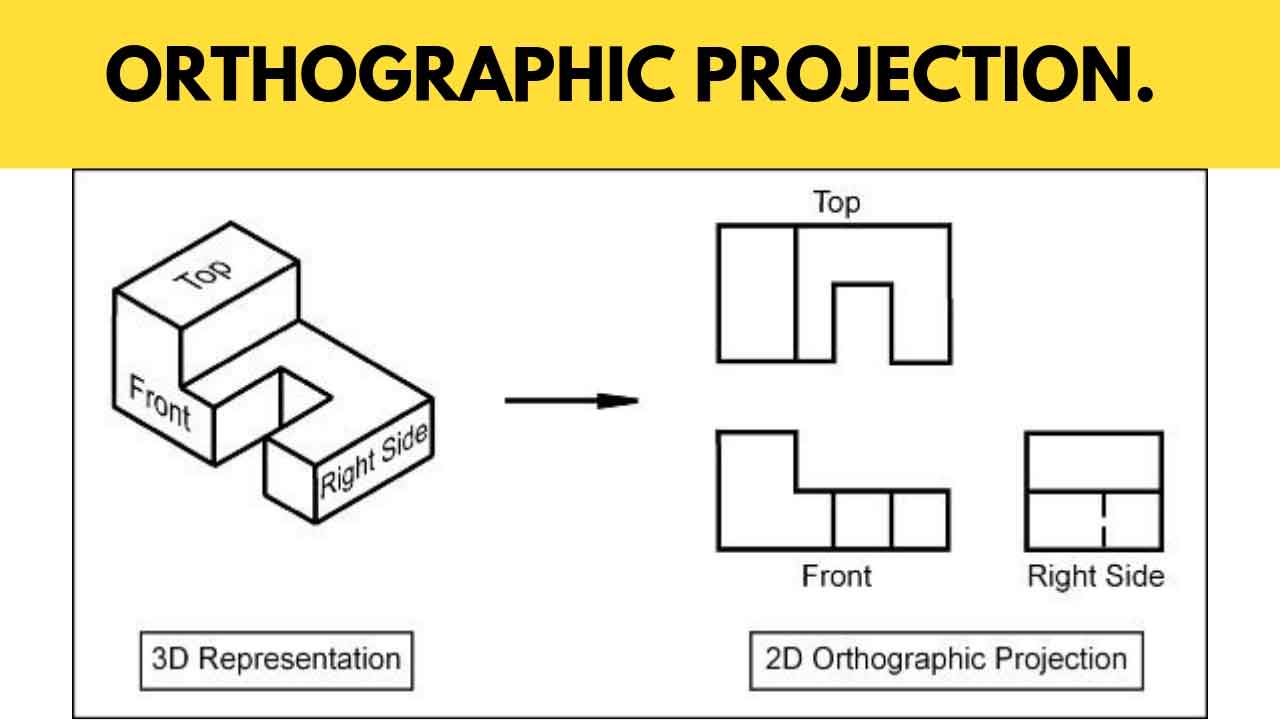
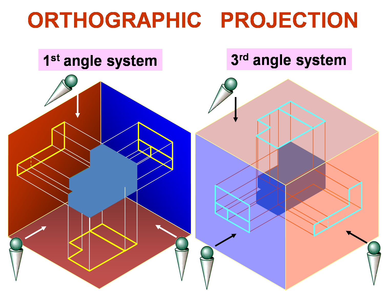
Projection Drawing - It is possible, of course, to select other views such as the left side or bottom, but you should have a good reason to do so. The projection of the data frame is changed. The three views selected are the top, front, and right side for the third angle projection used commonly in north america. One view is drawn, and lines are projected from it to generate the other views. As a result, the 3d object is transformed into a 2d view. Web to find the length of the edges in the isometric projection: 1st angle projection and 3rd angle projection are also part of the orthographic projections. D’c is the actual length of the edge, whereas corresponding edge d’c’ in the. This is such a type of drawing in which parallel projection is used for the preparation of the drawing of an object. To find the extent to which the lengths of the edges are foreshortened. This is such a type of drawing in which parallel projection is used for the preparation of the drawing of an object. Various types of projections in engineering drawings It has mainly two types, like multiview projections and axonomeric projections. Typically in axonometric drawing, as in other types of pictorials, one axis of space is shown to be vertical. There. In the lower window, click predefined > projected coordinate systems > utm > wgs 1984 and select utm zone 18n as the projection. D’c is the actual length of the edge, whereas corresponding edge d’c’ in the. Typically in axonometric drawing, as in other types of pictorials, one axis of space is shown to be vertical. Web in this video. Alternatively, some parts can be only simulated in model form. Web understanding the difference between first angle and third angle projection can help prevent costly mistakes and is crucial to being a good engineer. Web all of my drawings are printing slightly off scale. An object is placed in front of a plane of projection and an observer is at. Btw #1, #2, and #5 are projectors made specifically for artists, tracing, canvas painting, and murals. D’c is the actual length of the edge, whereas corresponding edge d’c’ in the. Web understanding the difference between first angle and third angle projection can help prevent costly mistakes and is crucial to being a good engineer. A wall length that should scale. The other projection type is the parallel projection in which the projector lines are parallel. Web to find the length of the edges in the isometric projection: It’s just not a single technique. Web understanding the difference between first angle and third angle projection can help prevent costly mistakes and is crucial to being a good engineer. Web the most. A wall length that should scale 20’ scales at about 18’6. These lines are perpendicular to the plane. Every drawing prints slightly smaller. I hope it helps you get the right one for your art, too! There are three types of pictorial views: This video is from the book engineering graphics essentials. It is possible, of course, to select other views such as the left side or bottom, but you should have a good reason to do so. Web in orthographic projection, the views are seen in directions that make right angles (i.e. Orthographic projection is a common technique to present a 3d. These lines are perpendicular to the plane. Web to find the length of the edges in the isometric projection: Web projections are created on a 2d surface, often technical drawing paper, that represent a 3d model. Web types of views used in drawings. These are 2d construction drawings i have originated in sketchup pro 2023 and sent to layout to. Web understanding the difference between first angle and third angle projection can help prevent costly mistakes and is crucial to being a good engineer. In the lower window, click predefined > projected coordinate systems > utm > wgs 1984 and select utm zone 18n as the projection. As a result, the 3d object is transformed into a 2d view. The. There is a strong chance you will have seen symbols like this on an engineering drawing: Orthographic projection is a form of parallel projection in which the top, front, and side. A plane is an imaginary surface on. Btw #1, #2, and #5 are projectors made specifically for artists, tracing, canvas painting, and murals. What is orthographic projection system? Web for engineering applications, the orthographic projection is the tool of choice in most cases. Mathematically, an orthographic projection is created by defining a flat projection plane, and then projecting the features of the 3d object onto the plane along lines (or projectors) which are perpendicular to the. I hope it helps you get the right one for your art, too! Web all of my drawings are printing slightly off scale. These are 2d construction drawings i have originated in sketchup pro 2023 and sent to layout to finish with dimensions and text. In technical drawings, projectors simulate a 3d part’s view onto the projection plane. The two main types of views (or “projections”) used in drawings are: These projections rely on visual perspective and aspect analysis to project a. In the lower window, click predefined > projected coordinate systems > utm > wgs 1984 and select utm zone 18n as the projection. Web in general, there are two main projection types in technical drawing. Web in the lower window, labeled select a coordinate system, a different coordinate system can be selected to display data in the data frame. The number of views needed should be sufficient to represent the object. 90 degrees) with each other. The other projection type is the parallel projection in which the projector lines are parallel. Web the most common orthographic projection drawings usually have three views. The first one is the perspective projection in which the projectors are starting from a point(observer’s eye) to each point of part.
ORTHOGRAPHIC PROJECTION IN ENGINEERING DRAWING FUNDAMENTAL YouTube
Orthographic Projection from isometric view in Engineering drawing
Build A Tips About How To Draw First Angle Projection Originalcurrency
ORTHOGRAPHIC PROJECTION IN ENGINEERING DRAWING YouTube
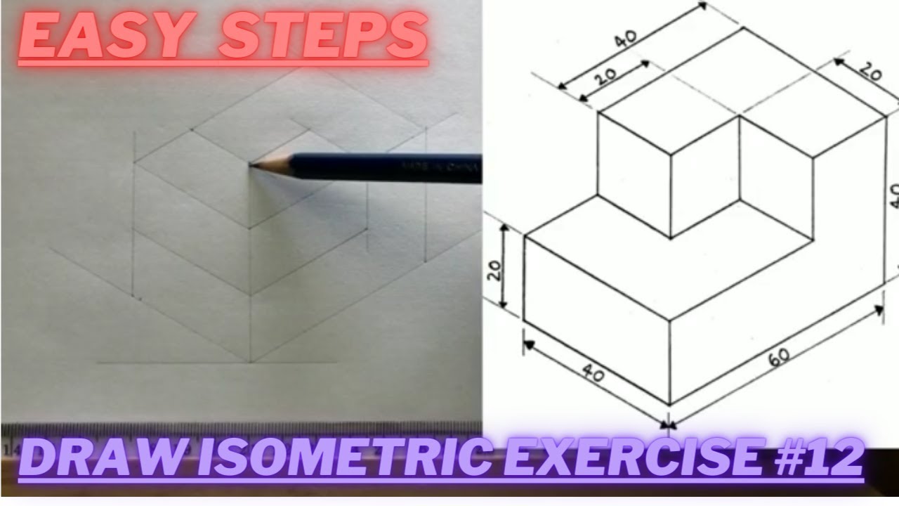
How to draw ISOMETRIC PROJECTIONS Technical Drawing Exercise 12
Orthographic Projection, Drawing A Comprehensive Guide.
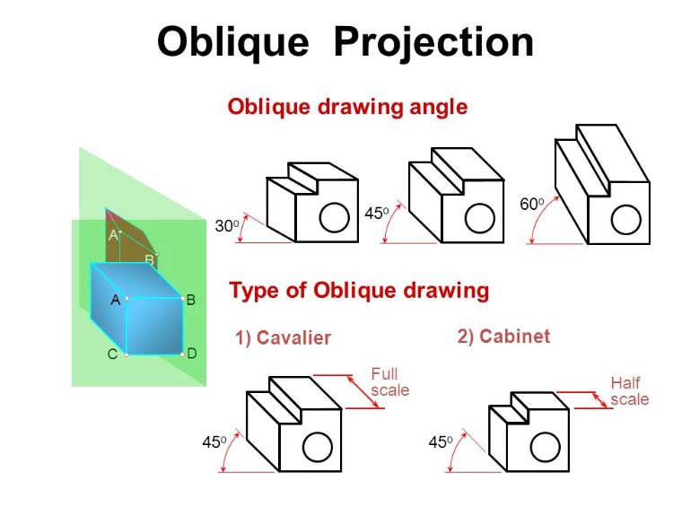
Oblique Drawing, Projection its Types, Examples. CivilSeek
What Is 3rd Angle Projection In Engineering Drawing Design Talk

Basic Engineering Drawing Projection Knowledge Zone, The Online Support

Basic Engineering Drawing Projection Knowledge Zone, The Online Support
Web To Find The Length Of The Edges In The Isometric Projection:
The Three Views Selected Are The Top, Front, And Right Side For The Third Angle Projection Used Commonly In North America.
A Plane Is An Imaginary Surface On.
1St Angle Projection And 3Rd Angle Projection Are Also Part Of The Orthographic Projections.
Related Post: