Potentiometer Drawing
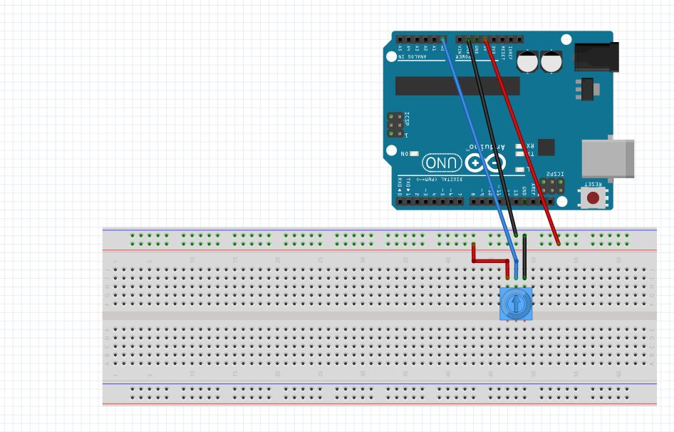
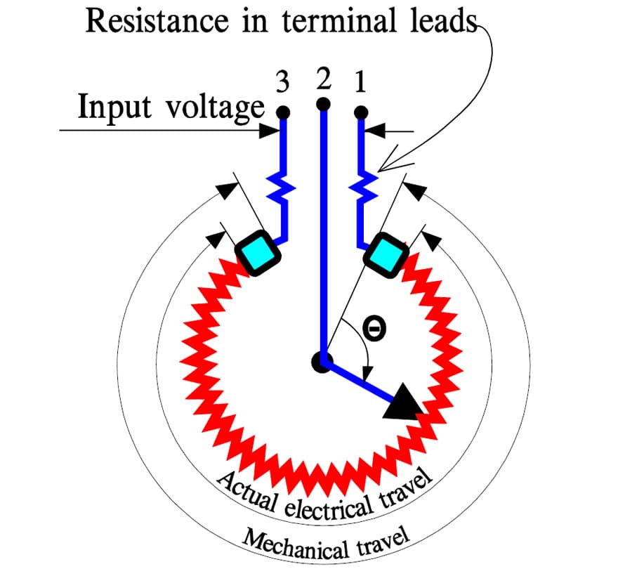
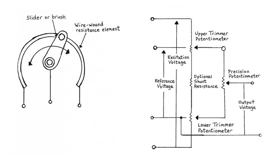
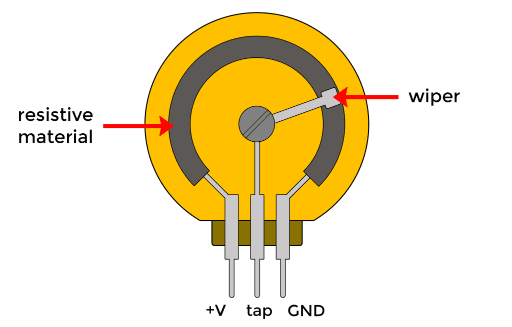
Potentiometer Drawing - Web complete circuit color mixer example this example will show you how a potentiometer can be used as an analog input to mix colors with great granularity. Carefully build this circuit on a breadboard or other convenient medium. They are used in a wide range of applications, including audio equipment, lighting systems, and. It is very versatile in nature. Check the accuracy of the circuit’s construction, following each wire to each connection point, and verifying these elements one. The principle of operation of a potentiometer is based on the notion that the drop in potential across any piece of a wire is exactly proportional to the wire’s length. As potentiometers have three terminals, the arrow represents the third terminal (the wiper). Web the potentiometer circuit diagram consists of: Web the mega millions jackpot passed $500 million ahead of friday night's drawing, after no one won the grand prize on tuesday night. A mechanical stop ( h) prevents rotation past end points. A salt bridge containing an inert electrolyte. Web a potentiometer is an instrument for measuring voltage or 'potential difference' by comparison of an unknown voltage with a known reference voltage. The quarter final draw is as follows: Web maximum input voltage: We all are familiar with resistors. A potentiometer can measure voltages, with higher accuracy than a voltmeter, without drawing a current from the main circuit. A resistor, a bundle of resistance, is one of the commonly used components in an electric circuit. A shaft carries the wiper, which is just a. Web a potentiometer circuit diagram is a graphical representation of the components used in a. Two terminals (the blue and green) are connected to a resistive element and the third terminal (the black one) is connected to an adjustable wiper. 10 11 12 13 int redpin = 9; A mechanical stop ( h) prevents rotation past end points. Web complete circuit color mixer example this example will show you how a potentiometer can be used. A mechanical stop ( h) prevents rotation past end points. 10 11 12 13 int redpin = 9; Carefully build this circuit on a breadboard or other convenient medium. Web maximum input voltage: It is very versatile in nature. These versatile devices play a pivotal role in controlling and measuring electrical signals, providing a dynamic interface between circuits and the physical world they interact with. The iec standard symbol for the potentiometer is a rectangle between two straight lines and the ansi standard potentiometer symbol. They are simple electrical devices which resist the flow of current in a circuit.. Web a potentiometer circuit diagram is a graphical representation of the components used in a potentiometer circuit, such as resistors, transistors, and capacitors. As potentiometers have three terminals, the arrow represents the third terminal (the wiper). Check the accuracy of the circuit’s construction, following each wire to each connection point, and verifying these elements one. Web the potentiometer circuit diagram. A potentiometer has 3 pins. As potentiometers have three terminals, the arrow represents the third terminal (the wiper). ( a) shaft, ( b) stationary carbon composition resistance element, ( c) phosphor bronze wiper, ( d) shaft attached to wiper, ( e, g) terminals connected to ends of resistance element, ( f) terminal connected to wiper. The purpose of a potentiometer. Alternative variable resistor resistors, trimmers, trimpot selecting a potentiometer potentiometers also known as pot, are nothing but variable resistors. Often used to regulate the current flow either by adding or subtracting resistance from the circuit, resistors are available in several different shapes and sizes. A potentiometer has 3 pins. The diagram to the left shows the standard symbol for a. How does a potentiometer work? The diagram to the left shows the standard symbol for a potentiometer as it would appear in a schematic. The winning numbers were drawn around 11 p.m. It is very versatile in nature. Web in this guide, i’ll show you what the potentiometer looks like on the inside, the different potentiometer types, and examples of. The potentiometer consists of l which is a long resistive wire and a battery of known emf v, whose voltage is known as driver cell voltage. A mechanical stop ( h) prevents rotation past end points. Web complete circuit color mixer example this example will show you how a potentiometer can be used as an analog input to mix colors. Whereas its pinout may vary depending on the potentiometer type you have (linear, rotary, or digital). The quarter final draw is as follows: A salt bridge containing an inert electrolyte. A shaft carries the wiper, which is just a. Web the mega millions jackpot passed $500 million ahead of friday night's drawing, after no one won the grand prize on tuesday night. Carefully build this circuit on a breadboard or other convenient medium. A potentiometer is a passive electronic component. ( a) shaft, ( b) stationary carbon composition resistance element, ( c) phosphor bronze wiper, ( d) shaft attached to wiper, ( e, g) terminals connected to ends of resistance element, ( f) terminal connected to wiper. There are many applications of a potentiometer, from audio controller circuit to measuring distances, angle or voltages. Web maximum input voltage: Web cutaway drawing of potentiometer showing parts: Web potentiometer diagram the potentiometer has two symbols, one of them is considered as its international standard symbol and the other one is the american symbol used to show potentiometers. Alternative variable resistor resistors, trimmers, trimpot selecting a potentiometer potentiometers also known as pot, are nothing but variable resistors. The diagram to the left shows the standard symbol for a potentiometer as it would appear in a schematic. Web the potentiometer circuit diagram consists of: A resistor, a bundle of resistance, is one of the commonly used components in an electric circuit.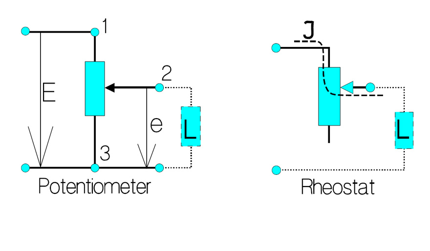
Basic Principles of Potentiometers/Variable Resistors

1/4" Smooth Shaft Potentiometer Right Angle PCB
Potentiometer Schematic Technology Tutorials
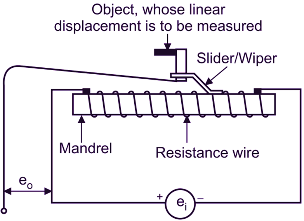
What is Linear Potentiometer? Working, Diagram & Explanation
Potentiometers Basic Principles
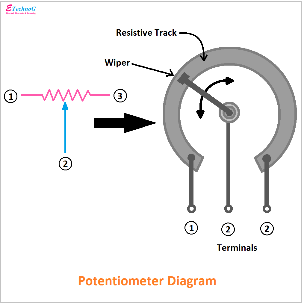
Potentiometer Diagram, Symbol, and Construction ETechnoG

potentiometer_diagram Electronics Go
Potentiometers Basic Principles
Multi Turning Control Potentiometer Design Guide eti
How to Use Potentiometers on the Arduino Circuit Basics
The Potentiometer Symbol Comprises A Resistor Symbol With An Arrow In The Middle.
It Is An Electronic Device Or An Instrument Used To Measure The Electric Current Flowing Through An Electric Circuit.
10 11 12 13 Int Redpin = 9;
Whenever There Is No Potential.
Related Post: