Draw Shear And Moment Diagrams
Draw Shear And Moment Diagrams - Web shear force and bending moment diagrams are powerful graphical methods that are used to analyze a beam under loading. You'll get a detailed solution from a subject matter expert that helps you learn core concepts. Draw the shear and moment diagrams for the beam. Web steps to construct shear force and bending moment diagrams. Web learn to draw shear force and moment diagrams using 2 methods, step by step. Skyciv beam tool guides users along a professional beam calculation workflow, culminating in the ability to view and determine if they comply with your region's design codes. This page will walk you through what shear forces and bending moments are, why they are useful, the procedure for drawing the diagrams and some other keys aspects as well. Once you have the reactions, draw your free body diagram and shear force diagram underneath the beam. Find the support reaction forces/moments. Web the quickest way to tell a great cv writer from a great graduate engineer is to ask them to sketch a qualitative bending moment diagram for a given structure and load combination! Has graph paper, study tips, and some sudoku puzzles or downtime between classes! Draw a fbd of the structure. 20 kn 40 kn/m cl 150 kn m 8 m 3 m prob. They allow us to see where the maximum loads occur so that we can optimize the design to prevent failures and reduce the overall weight and cost of. 1) calculate support reactions 2) draw vertical. Web you'll get a detailed solution from a subject matter expert that helps you learn core concepts. Calculate the reactions using the equilibrium equations (may not need to do this if choosing a cantilever beam and using the free side for the fbd). Web learn to draw shear force and moment diagrams using. There are 2 steps to solve this one. Has graph paper, study tips, and some sudoku puzzles or downtime between classes! Draw a fbd of the structure. Draw a free body diagram of the beam with global coordinates (x) calculate the reaction forces using equilibrium equations ( ∑ forces = 0 and ∑ moments = 0 ). The calculator is. Skyciv beam tool guides users along a professional beam calculation workflow, culminating in the ability to view and determine if they comply with your region's design codes. Web you'll get a detailed solution from a subject matter expert that helps you learn core concepts. Web 𝐌𝐲 𝐄𝐧𝐠𝐢𝐧𝐞𝐞𝐫𝐢𝐧𝐠 𝐍𝐨𝐭𝐞𝐛𝐨𝐨𝐤 for notes! Draw the shear and moment diagrams for the beam. So. The moment can be calculated at any point by integrating the shear diagram. 1) calculate support reactions 2) draw vertical. Web calculating bending moment diagram by hand. Introduction notations relative to “shear and moment diagrams” e = modulus of elasticity, psi i = moment of inertia, in.4 l = span length of the bending. Web plots of v(x) v (. 1) calculate support reactions 2) draw vertical. So in this post we’ll give you a thorough introduction to shear forces, bending moments and how to draw shear and moment diagrams. Web our calculator generates the reactions, shear force diagrams (sfd), bending moment diagrams (bmd), deflection, and stress of a cantilever beam or simply supported beam. A moment diagram is drawn. There is a long way and a quick way to do them. Being able to draw shear force diagrams (sfd) and bending moment diagrams (bmd) is a critical skill for any student studying statics, mechanics of materials, or structural engineering. Web 𝐌𝐲 𝐄𝐧𝐠𝐢𝐧𝐞𝐞𝐫𝐢𝐧𝐠 𝐍𝐨𝐭𝐞𝐛𝐨𝐨𝐤 for notes! Has graph paper, study tips, and some sudoku puzzles or downtime between classes! Web. There are 2 steps to solve this one. This page will walk you through what shear forces and bending moments are, why they are useful, the procedure for drawing the diagrams and some other keys aspects as well. Find the support reaction forces/moments. We will refer to them as we go through the following main steps in each example: Web. Web 𝐌𝐲 𝐄𝐧𝐠𝐢𝐧𝐞𝐞𝐫𝐢𝐧𝐠 𝐍𝐨𝐭𝐞𝐛𝐨𝐨𝐤 for notes! Introduction notations relative to “shear and moment diagrams” e = modulus of elasticity, psi i = moment of inertia, in.4 l = span length of the bending. Draw the shear and moment diagrams for the beam. Lined up below the shear diagram, draw a set of axes. Web draw the shear force and bending. Calculate the reactions using the equilibrium equations (may not need to do this if choosing a cantilever beam and using the free side for the fbd). Being able to draw shear force diagrams (sfd) and bending moment diagrams (bmd) is a critical skill for any student studying statics, mechanics of materials, or structural engineering. Also, draw shear and moment diagrams,. Draw a free body diagram of the beam with global coordinates (x) calculate the reaction forces using equilibrium equations ( ∑ forces = 0 and ∑ moments = 0 ). Wall reactions for the cantilevered beam. We go through breaking a beam into segments, and then we learn about the relationships between shear force. There is a long way and a quick way to do them. Also, draw shear and moment diagrams, specifying values at all change of loading positions and at points of zero shear. Neglect the mass of the beam in each problem. Calculate the reactions using the equilibrium equations (may not need to do this if choosing a cantilever beam and using the free side for the fbd). Web shear and moment diagrams and formulas are excerpted from the western woods use book, 4th edition, and are provided herein as a courtesy of western wood products association. Once you have the reactions, draw your free body diagram and shear force diagram underneath the beam. Skyciv beam tool guides users along a professional beam calculation workflow, culminating in the ability to view and determine if they comply with your region's design codes. Web plots of v(x) v ( x) and m(x) m ( x) are known as shear and bending moment diagrams, and it is necessary to obtain them before the stresses can be determined. Web shear force and bending moment diagrams are powerful graphical methods that are used to analyze a beam under loading. Web write shear and moment equations for the beams in the following problems. Web draw the shear force and bending moment diagrams for the cantilever beam supporting a concentrated load of 5 lb at the free end 3 ft from the wall. Web solve for all external forces and moments, create a free body diagram, and create the shear diagram. 1) calculate support reactions 2) draw vertical.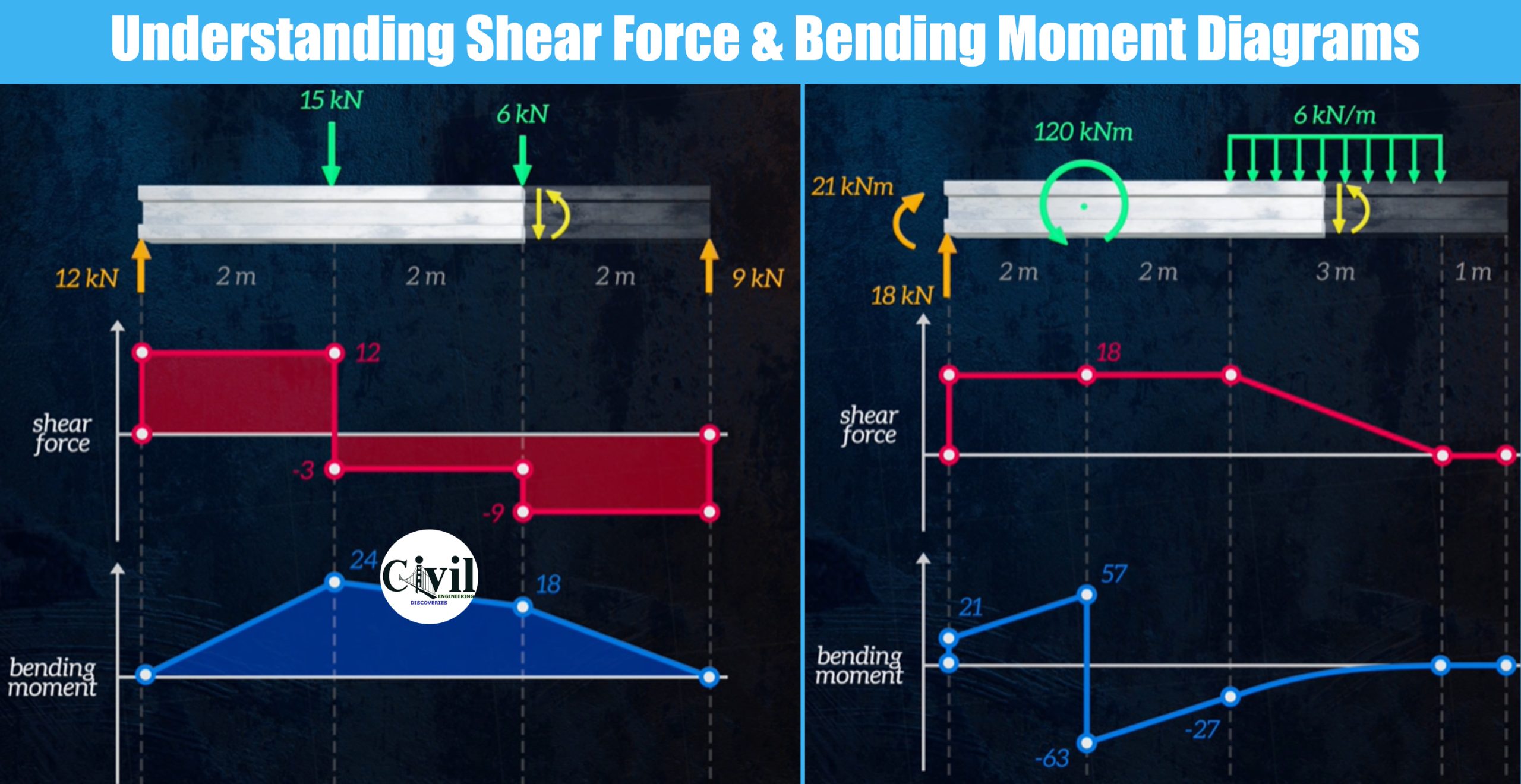
Understanding Shear Force And Bending Moment Diagrams Engineering

Shear and moment diagrams indimg

Learn How To Draw Shear Force And Bending Moment Diagrams Engineering

Brief Information About Shear Force And Bending Moment Diagrams

How to draw shear and moment diagrams YouTube
The Ultimate Guide to Shear and Moment Diagrams

Drawing Shear and Moment Diagrams for Beam YouTube

Solved Draw The Shearforce And Bendingmoment Diagrams F...

The Ultimate Guide to Shear and Moment Diagrams

Learn How To Draw Shear Force And Bending Moment Diagrams Engineering
We Will Refer To Them As We Go Through The Following Main Steps In Each Example:
In General The Process Goes Like This:
Introduction Notations Relative To “Shear And Moment Diagrams” E = Modulus Of Elasticity, Psi I = Moment Of Inertia, In.4 L = Span Length Of The Bending.
All Afds, Sfds, And Bmds Follow These Basic Rules.
Related Post: